Basic knowledge of protective board (PCB)
1. Classification of protective boards
1. Double protection board: called double control board. It has overcharge, over-discharge, over-current and short-circuit protection.
2. Single protection board: also called single control board. Only has overcharge protection.
3. Through board: also called fake board.
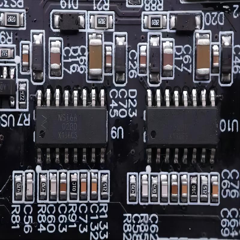
2. Understanding and identification of PCB patches
1. The protection board mainly contains control IC, MOS, resistors, capacitors, etc. Some of them have decoding chips.
2. Several commonly used ICs: 5421, DW01, SC451, JW11, etc. MOS mainly includes 9926, 5N20V, etc. Resistors are 101/471, 102/471. Capacitors are 104 and 103.
3. Calculation of resistance and capacitance values:
Calculation method of resistance: For example, the resistance value of 101 is 10*101 =10*10=100 ohms. That is, the first two digits of 101 do not change to 10, and the following 1 is a power number, which is 101. For another example, the resistance value of 103 is 10*103 =10*1000=10K ohms. The calculation method of capacitance is the same as above. For example; 103 capacitance value 10*103 *10-6=0.01uf
3. The main function of PCB patches
1. Control IC: detection and control of overcharge protection, over-discharge protection, over-current protection and short-circuit protection.
Control ICs from different manufacturers only have different control accuracy and voltage, and most of the tube angle function definitions are basically the same. Its pins are: ①DOUT: over-discharge protection output: ②V-: charging negative input ③COUT: overcharge protection output ④CT: external capacitor setting delay time ⑤VDD: power supply port ⑥VSS ground terminal.
2. MOS tube: a reception device that protects the action of the board. Just think of it as a controllable switch with low internal resistance.
3. 101/471 resistor: plays the dual role of current limiting and power supply to the control IC in the circuit.
4. 102/471 resistor: sampling resistor, returns the output P-voltage to the control IC.
5. 104 capacitor: It is mainly an anti-interference capacitor connected to the 101 and 102 resistors.
6.103 Capacitor: Delay capacitor required by the control IC.
The protection circuit of lithium-ion batteries is roughly the same, but it lacks the safety protection of TH (thermistor) in terms of temperature rise, and some also require ID (identification) resistors and decoding chips.
4. PCB board parameters
Only for dual control boards, overcharge protection voltage: between 4.25-4.35V:
Over-discharge protection voltage: between 2.43-2.56: Short-circuit protection current: between 2-6A:
Static power consumption: less than or equal to 6uA: overcharge time: between 140-210ms:
Over-discharge delay: between 7-13ms: Short-circuit delay: less than or equal to 50us:
5. Understanding of thermistors, ID resistors, and decoding chips
1. The thermistor is not used for protection. It is connected to an AD port inside the mobile phone. When the temperature is higher or lower than a certain value, it will remind the MCU module in the mobile phone that it is overtemperature or too cold, and take corresponding actions. What really plays a protective role is PTC or FUSE.
2. ID resistor is a mobile phone's identification of the battery type. Some mobile phones use different ID resistor values to identify the battery type\capacity and other information. Then according to the specific battery, it adopts the corresponding charging mode to charge it. This type of resistor The working method of the thermistor is basically similar to that of a thermistor. A fixed resistor is connected in series with a voltage base inside the mobile phone, and then the divided voltage value of the resistor and the voltage on the battery are transmitted to the AD port of the mobile phone MCU module for collection, identification and processing. .
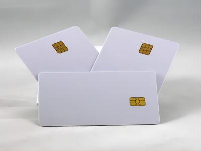
3. The original lithium battery of mobile phones will have a code chip. This code belongs to the I=wire protocol type. It contains certain information and is widely used. It is equivalent to an identity recognition on the mobile phone. Without it, the mobile phone cannot be recognized and cannot be turned on. machine.
6. Overcharge protection
The charging method required for ion batteries is constant current/constant voltage. In the initial stage of charging, constant current charging is used. As charging proceeds, the voltage will rise to 4.2V) (depending on the positive electrode material, some batteries require a constant voltage of 4.1V ), switch to constant voltage charging until the current becomes smaller and smaller. When the battery is being charged, if the charger circuit loses control, the voltage will exceed 4.2V and then constant current charging will continue. At this time, the battery voltage will continue to rise. When the battery voltage is charged above 4.3V, the chemical side reactions of the battery will intensify, causing battery damage or safety issues, destroying the reversible chemical reaction of the battery, and seriously shortening the battery life.
In a battery with a protection circuit, when the control IC detects that the battery voltage reaches 4.25 (this value is determined by the control IC, and different ICs have different values), its ""CO"" pin will change from high voltage to zero voltage. Make the MOS switch from conduction to disconnection at the beginning of charging, thereby cutting off the charging circuit and preventing the charger from charging the battery, which plays a protective role. When the control IC detects that the battery voltage exceeds 4.25V and turns off the circuit, there is A delay time, which is determined by C3 and is usually set to about 1 second to avoid interference and misjudgment.
7. Over-discharge protection
When the battery discharges the external load, its voltage will gradually decrease with the discharge process. When the battery voltage drops to 2.75V, its capacity has almost been completely discharged. At this time, if the battery continues to discharge the load, it will cause Permanent damage to the battery. During the discharge process, when the control IC detects that the battery voltage is lower than 2.75V (this value is determined by the control IC, different ICs have different values), its ""DO"" pin will switch from high voltage to is zero voltage, causing the MOS discharge switch to turn from on to off, cutting off the discharge circuit, making the battery unable to discharge the load, and playing the role of over-discharge protection. Since the battery voltage cannot be reduced in the over-discharge protection state: therefore The current consumption of the protection circuit is required to be extremely small. At this time, the control IC will enter a low power consumption state, and the power consumption of the entire protection circuit will be less than 0.1uA. There will be a period of time after the control IC detects an overcurrent and the MOS pin is disconnected. This extension The length of time is determined by C3, usually around 13MS, to avoid interference and misjudgment.
8. Over-current protection
In the normal discharge state, when the discharge current reaches or exceeds the overcurrent detection current and this state continues beyond the overcurrent detection delay time, the ""DO"" pin of the protection IC outputs a low level and turns off the MOS discharge switch of the discharge control. , stop discharging. When the impedance between P+ and P- reaches above the automatic recovery impedance, the overcurrent state is restored. There is also a delay time between when the control IC detects overcurrent and when the MOS pin is disconnected. The length of this delay time is determined by C3, usually about 13ms, to avoid interference and cause erroneous judgments.
9. Short circuit protection
When the battery is discharging the load, if the loop current reaches U>0.9A (this value is determined by the IC), the control IC determines that the load is short-circuited, and its ""DO"" pin quickly changes from high voltage to zero voltage, causing the MOS to be cut off. Discharge circuit plays a protective role. The delay time of short circuit protection is very short, usually less than 7us
10. Internal resistance of PCB
Through the above analysis, it is not difficult to know that the internal resistance of the PCB is mainly caused by the internal resistance of the MOS and the recoverable fuse (the internal resistance of the other vitality parts is very small and can be ignored). Since the Canyon MOSFETs are used in series, the internal resistance of the two tubes should be calculated to be generally about 20MΩ each. The internal resistance value of the resettable fuse varies depending on the metal and current used, but is generally about 10-30mΩ. Therefore, the internal resistance of the entire board is about 70mΩ or less. Based on the above, we might as well calculate the internal resistance of the entire battery block: the internal resistance of the A-grade battery is generally 40MΩ, the protection board is generally 60mΩ, and the connection is generally around 30mΩ, then the total internal resistance of the battery block is about 130MΩ.
11. PCB board inspection standards
1. The appearance is free of debris and residue.
2. The hardware is free of scratches, rust, discoloration and other defects, and whether it matches the bracket.
3. Is there any defective soldering of components such as desoldering, false soldering, or false soldering?
4. There must be no lack of components, identification resistors, thermistors, chips, etc.
5. Whether the size of the board and the actual size are within the allowable error, and whether they match the plastic shell.
6. Identify whether the board is a single control board or a dual control board, don't get confused.
12. Detection instrument
The protective board usually uses a lithium battery. The protective board test is recommended to be measured according to the corresponding parameters. If the product is not within this range, it is a defective product and will be dealt with accordingly. The commonly used protection board test we use now is Lithium Yi'an, which is simple to operate. Accurate measurement